
CS SERIES
Cylindrical feeder bowls
Bowl geometry, spiral track and orientation tooling are selected for the component and production process.
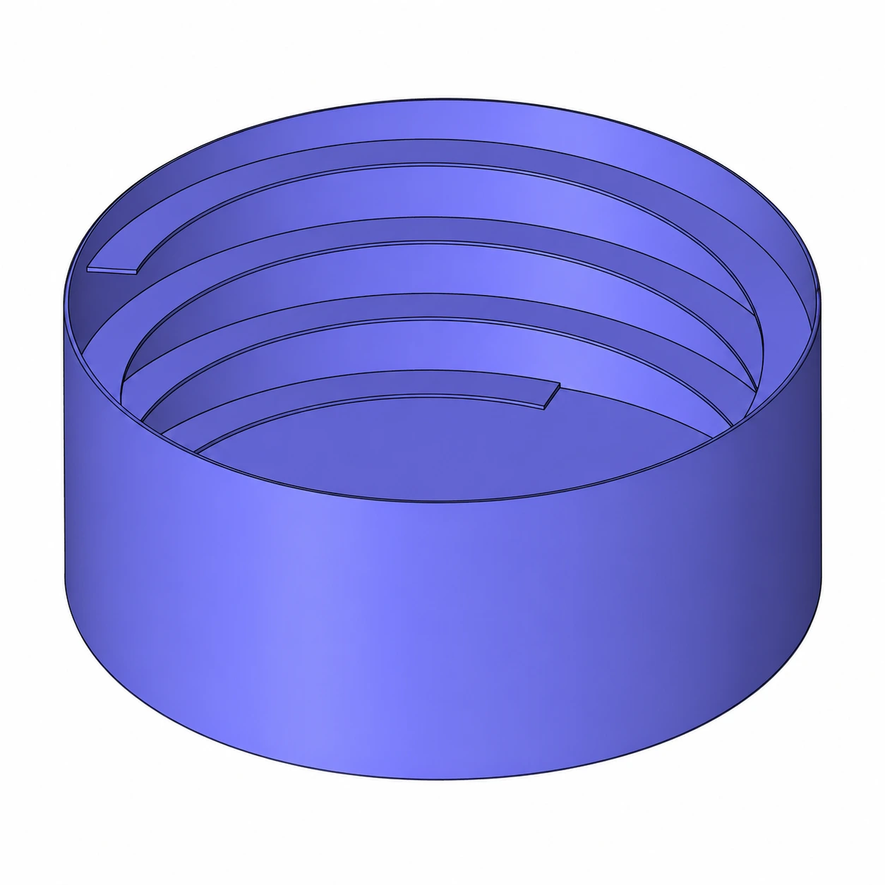
BOWL GEOMETRY
Straight sides, an internal spiral track.
The CS series combines a cylindrical body with an internal spiral track. Component-specific tooling determines the discharge orientation. The CS 150 outside diameter is 155 mm in the original sheet.
- Track width matched to component geometry
- Orientation tooling for the required discharge position
- Application-specific contact surface and coating
- Drive-unit and mounting compatibility
ORIGINAL DIMENSIONS
Drawing and model comparison.
Use the lettered dimensions in the drawing together with the table. Rise dimensions are in mm; they are not angle values.
| Specification / unit | CS 100 | CS 150 | CS 200 | CS 280 | CS 400 | CS 500 | CS 650 |
|---|---|---|---|---|---|---|---|
Bowl outside diameter A (mm) | 100 | 155 | 200 | 280 | 400 | 500 | 650 |
Bowl height B (mm) | 50 | 80 | 100 | 120 | 160 | 240 | 280 |
Bowl wall thickness C (mm) | 2 | 2 | 2 | 2 | 2 | 2 | 2 |
Track rise dimension D (mm) | 15 | 25 | 30 | 40 | 60 | 80 | 90 |
Spiral track width E (mm) | 8 | 10 | 15 | 20 | 25 | 40 | 70 |
Spiral track thickness F (mm) | 1.5 | 1.5 | 1.5 | 1.5 | 2 | 2 | 2 |
Spiral start dimension G (mm) | 10 | 10 | 10 | 10 | 15 | 20 | 20 |
Spiral end dimension H (mm) | 10 | 15 | 15 | 20 | 25 | 40 | 40 |
Bottom thickness J (mm) | 1.5 | 1.5 | 2 | 2 | 2 | 2 | 2 |
Dimensions are approximate; deviations and technical changes are possible. Linear dimensions are in mm unless otherwise stated. Final configuration is confirmed for the application.
DISCUSS YOUR APPLICATION
Let us engineer the right feeding system for your component.
Send a component photo, drawing and target feed rate. We will evaluate the right configuration for your process.