
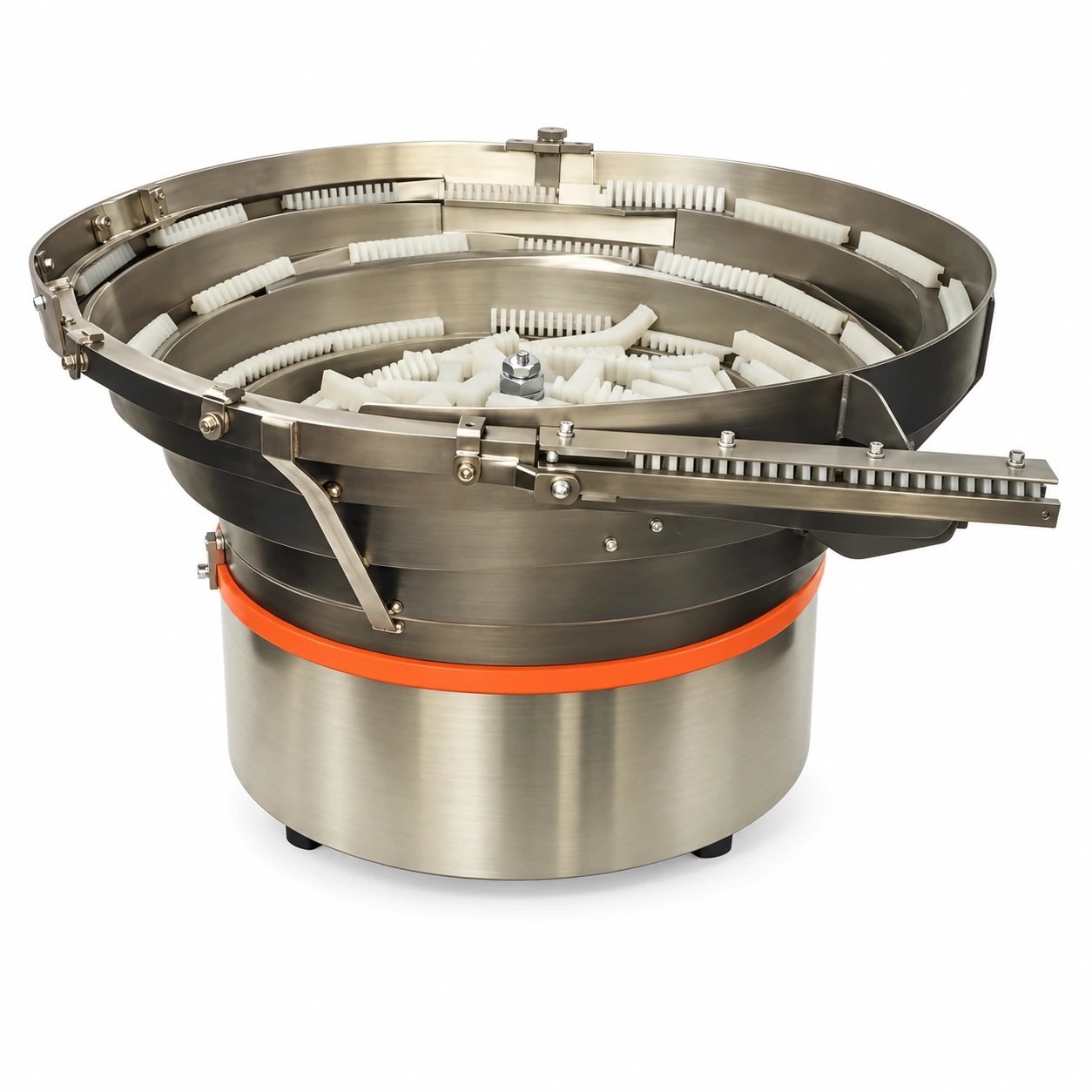
 Series example · model dimensions below
 TBS 280 S
TBS 280 S Vibratory Bowl Feeder
280 mm bowl diameter, 2.2 L volume and 200 VA power; orientation tooling is configured for the component.
View technical details →TBS SERIES
Separate, orient and feed bulk components into automated assembly, inspection and packaging processes.
APPLICATION ENGINEERING
An electromagnetic drive creates controlled vibration. A spiral track carries the components upwards while part-specific tooling rejects incorrect orientations and guides suitable parts to the outlet.
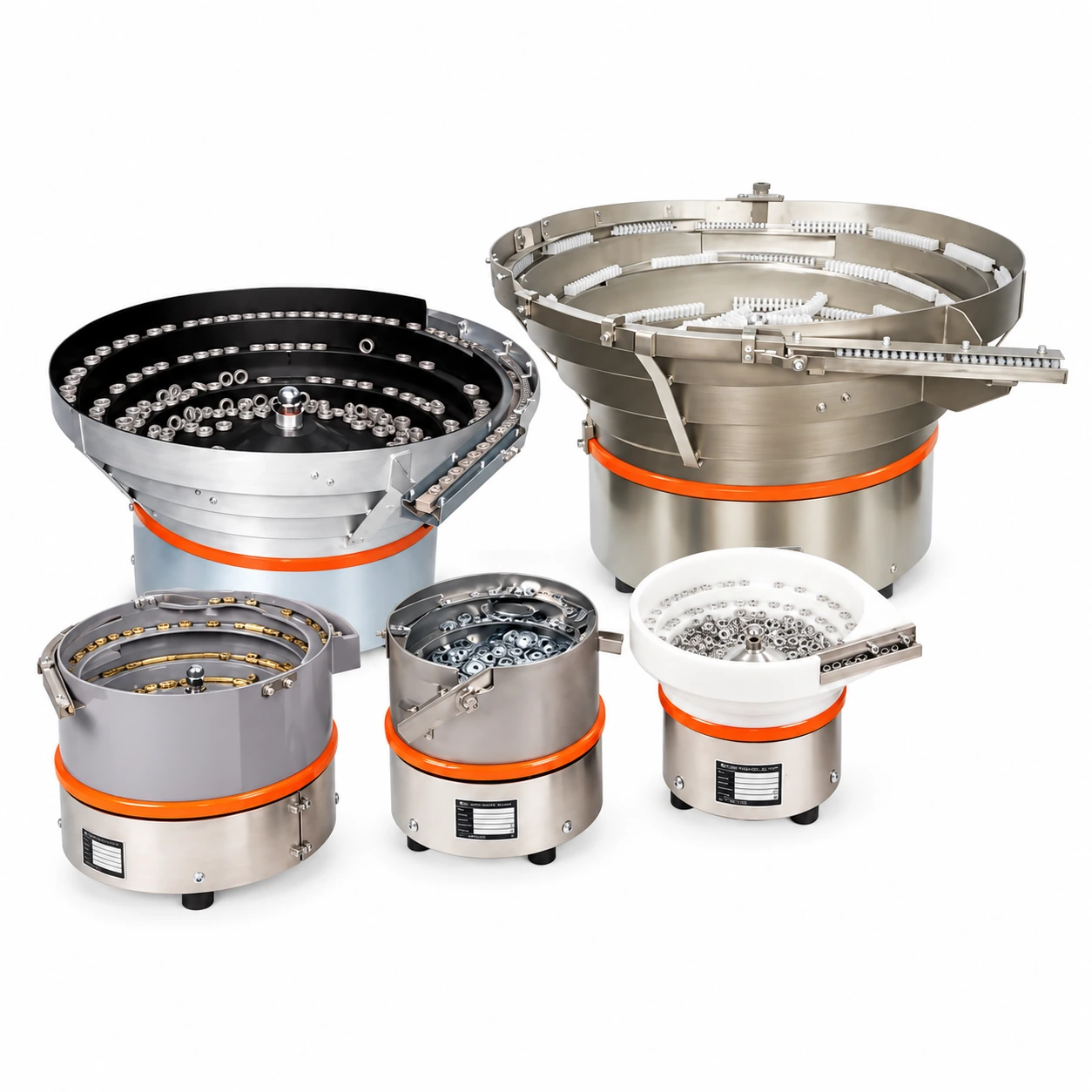
TUTUS CATALOGUE EXAMPLES
Selected TUTUS applications with different components, bowl forms and orientation tooling. Enhanced catalogue photographs illustrate application concepts; the original images can be opened from each gallery view.
STANDARD MODEL RANGE
Compare dimensions and electrical ratings, then review the selected model. Final selection considers the moving mass, component and required feed rate.
Series example · model dimensions below 280 mm bowl diameter, 2.2 L volume and 200 VA power; orientation tooling is configured for the component.
View technical details → Series example · model dimensions below 400 mm cylindrical bowl diameter, 6.5 L volume and 600 VA drive power.
View technical details → Series example · model dimensions below 500 mm bowl diameter and 16 L cylindrical bowl volume with a 1200 VA drive.
View technical details → Series example · model dimensions below 650 mm bowl diameter and 28 L cylindrical bowl volume with application-specific orientation tooling.
View technical details →DIMENSIONS & ELECTRICAL DATA
Select one model or compare the complete series. Tables can be exported to CSV for your project documentation.
| Specification / unit | TBS 280 S | TBS 400 S | TBS 500 S | TBS 650 S |
|---|---|---|---|---|
| Bowl diameter (ØD1) | 280 mm | 400 mm | 500 mm | 650 mm |
| Drive top plate (ØD2) | 290 mm | 410 mm | 510 mm | 665 mm |
| Lower connection (ØD3) | 230 mm | 340 mm | 430 mm | 560 mm |
| Foot diameter (ØD4) | 30 mm | 50 mm | 50 mm | 75 mm |
| Drive height (H1) | 130 mm | 165 mm | 202 mm | 235 mm |
| Foot height (H2) | 30 mm | 30 mm | 30 mm | 55 mm |
| Bowl height (H3) | 120 mm | 160 mm | 240 mm | 280 mm |
| Overall height (H4) | 250 mm | 325 mm | 442 mm | 515 mm |
| Outlet height (H5) | 220 mm | 285 mm | 395 mm | 470 mm |
| Outlet length (L1) | 140 mm | 200 mm | 240 mm | 300 mm |
| Foot thread (G1) | M8 | M10 | M10 | M12 |
| Bowl connection (G2) | M12 | M16 | M24 | M24 |
| Bowl volume | 2.2 L | 6.5 L | 16 L | 28 L |
| Electrical supply | 220 V · 50/60 Hz | 220 V · 50/60 Hz | 220 V · 50/60 Hz | 220 V · 50/60 Hz |
| Power / current | 200 VA / 1.1 A | 600 VA / 2.7 A | 1200 VA / 5.5 A | 1200 VA / 5.5 A |
| Foot mounting pattern (X/Y) | X | X | X | X |
Dimensions are approximate; deviations and technical changes are possible. Linear dimensions are in mm unless otherwise stated. Final configuration is confirmed for the application.
INTEGRATION OPTIONS
A drive is part of a complete solution: tracks, support structures, coatings and controls are selected for the application.
For oily or sensitive parts, evaluate the contact surface. Brushlon carpet coating is an available application option.
Define mounting height, outlet position and machine interface before selecting the support configuration.
Bowl level control and track sensing support coordinated replenishment and downstream delivery.
CONTACT SURFACES
The bowl contact surface is selected according to component material, surface condition and sensitivity. Brushlon carpet coating is one of the options used for oily components such as nuts. Final material selection is assessed with the real component.
APPLICATION QUESTIONS
Selection considers component geometry, bowl and part mass, surface condition, target feed rate and the required discharge orientation. A component sample or drawing is needed.
The current TBS range includes four models from TBS 280 S to TBS 650 S, with 280–650 mm bowl diameters and 2.2–28 L cylindrical bowl volumes. Custom applications require a separate technical assessment.
No. Volume describes bowl capacity. Output depends on the component, orientation tooling, part behaviour and the machine cycle. It is confirmed by application testing.
Surface condition and sensitivity determine the coating. Brushlon carpet coating is an option used for oily parts; the material is selected with the application.
DISCUSS YOUR APPLICATION
Send a component photo, drawing and target feed rate. We will evaluate the right configuration for your process.