
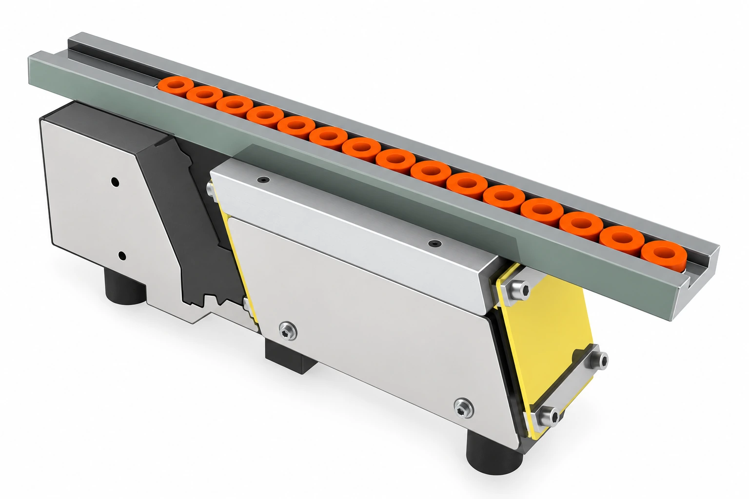
 Series example · model dimensions below
 VL 250
VL 250 Vibratory Linear Feeder
Controlled component transfer with 260 mm overall length, 60 VA power and 3 kg drive weight.
View technical details →VL SERIES
Transfer oriented parts from the bowl to the machine, maintain their position and build a controlled buffer.
APPLICATION ENGINEERING
The linear drive moves components along a track designed for their geometry. The track maintains orientation and provides a queue between the bowl and the next station.
TUTUS CATALOGUE EXAMPLES
Original TUTUS CAD examples show linear drive and track configurations. Model dimensions and electrical data are listed separately below.
STANDARD MODEL RANGE
Compare dimensions and electrical ratings, then review the selected model. Final selection considers the moving mass, component and required feed rate.
Series example · model dimensions below Controlled component transfer with 260 mm overall length, 60 VA power and 3 kg drive weight.
View technical details → Series example · model dimensions below Controlled component transfer with 465 mm overall length, 120 VA power and 5 kg drive weight.
View technical details → Series example · model dimensions below Controlled component transfer with 800 mm overall length, 600 VA power and 15 kg drive weight.
View technical details →DIMENSIONS & ELECTRICAL DATA
Select one model or compare the complete series. Tables can be exported to CSV for your project documentation.
| Specification / unit | VL 250 | VL 470 | VL 800 |
|---|---|---|---|
| Overall length (L1) | 260 mm | 465 mm | 800 mm |
| Nominal length (L2) | 250 mm | 470 mm | 800 mm |
| Mounting pitch (L3) | 210 mm | 340 mm | 600 mm |
| Body width (B1) | 73 mm | 95 mm | 200 mm |
| Track plate width (B5) | 45 mm | 56 mm | 100 mm |
| Body height (H1) | 60 mm | 72 mm | 160 mm |
| Overall height (H3) | 80 mm | 102 mm | 220 mm |
| Connection thread (G1) | M6 | M8 | M16 |
| Electrical supply | 220 V · 50/60 Hz | 220 V · 50/60 Hz | 220 V · 50/60 Hz |
| Power / current | 60 VA / 0.27 A | 120 VA / 0.55 A | 600 VA / 2.7 A |
| Support angle | 11° | 15° | 22° |
| Support thread | M8 | M10 | M16 |
| Locating bore | Ø8H7 | Ø8H7 | Ø16H7 |
| Thread count | 4 | 4 | 6 |
| Drive weight | 3 kg | 5 kg | 15 kg |
VL values are retained from the existing project technical dataset. Track length and driver length are different dimensions. Confirm dimensions, electrical ratings and moving load with the technical team before ordering.
INTEGRATION OPTIONS
A drive is part of a complete solution: tracks, support structures, coatings and controls are selected for the application.
For oily or sensitive parts, evaluate the contact surface. Brushlon carpet coating is an available application option.
Define mounting height, outlet position and machine interface before selecting the support configuration.
Bowl level control and track sensing support coordinated replenishment and downstream delivery.
APPLICATION QUESTIONS
No. The linear drive supports a separately designed track. The required track length and moving mass are assessed together with the drive configuration.
Mounting height, outlet position, track profile and the machine interface must be assessed. Sensors and stops can regulate the queue and match downstream demand.
Provide component dimensions, material, required orientation, parts per minute, available mounting space and the downstream machine cycle. Include a drawing or clear photographs.
DISCUSS YOUR APPLICATION
Send a component photo, drawing and target feed rate. We will evaluate the right configuration for your process.